Skylab Space Station - Main Components
Saturn V Instrument Unit (IU)

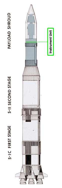
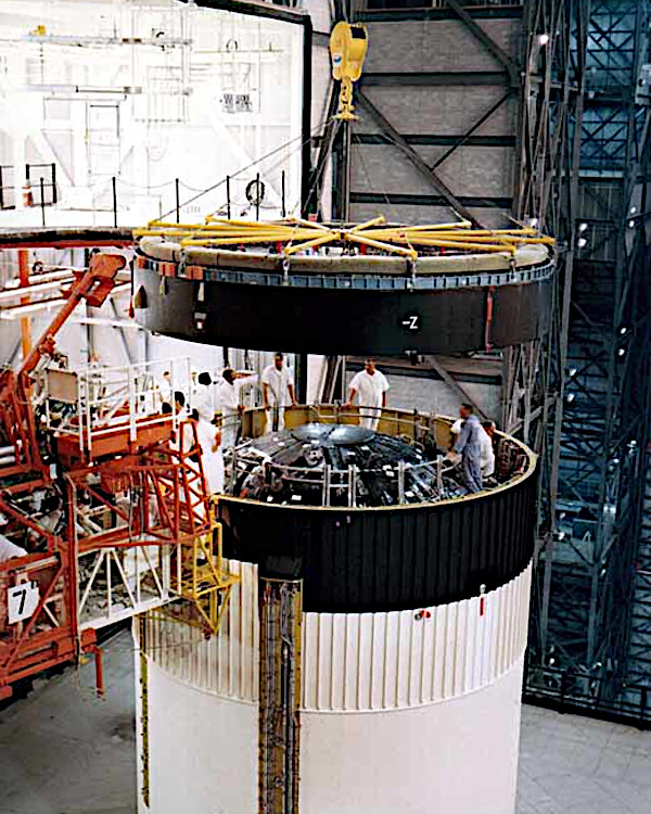
All Saturn V rockets used inertial guidance, a self-contained system that guided the rocket's trajectory. This was separate from those on the command and lunar modules. The guidance system was contained in the Instrument Unit (IU), a ring-shaped structure fitted to the top of the Saturn V rocket's third stage (S-IVB).
The IU was immediately below the Spacecraft/Lunar Module Adapter panels that contained the Apollo Lunar Module. It included a digital computer, analog flight control computer, emergency detection system, inertial guidance platform, control accelerometers, and control rate gyros.
The IU had a diameter of 6.6 m, height of 914 mm and a Weight at launch of ~1996 kg. Saturn I and IB rockets also used a similar IU on top of their second stage.
Reference: Wikipedia - Saturn V instrument unit.
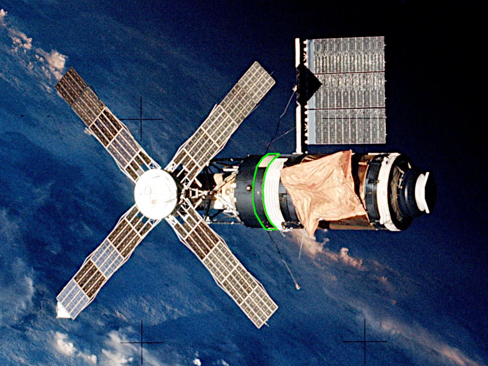
For the launch of Skylab the IU was also fitted to the top of the Saturn V rocket's third stage (S-IVB), below Skylab's Orbital Workshop module. The IU contained similar equipment to other Saturn V flights, configured to suit the Skylab mission. The following details are common to all IU systems.
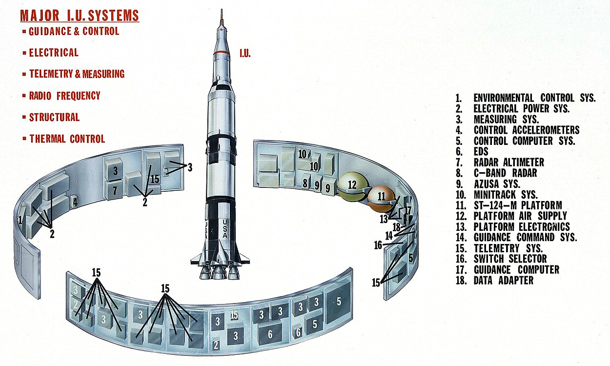
The IU consists of six subsystems: structure, guidance and control, environmental control, emergency detection, radio communications (for telemetry, tracking, and command), and power.
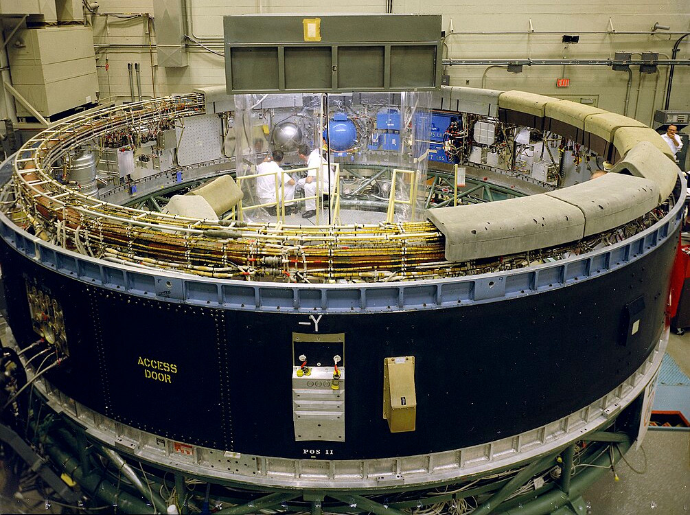
The basic IU structure is a short cylinder fabricated of an aluminum alloy honeycomb sandwich material 24 mm thick. The cylinder is manufactured in three 120-degree segments, which are joined by splice plates into an integral structure. The top and bottom edges are made from extruded aluminum channels bonded to the honeycomb sandwich.
This type of construction was selected for its high strength to weight ratio, acoustical insulation, and thermal conductivity properties. The IU supported the components mounted on its inner wall and the weight of the Apollo spacecraft above.
The IU is divided into 24 locations, which are marked on the interior by numbers 1 to 24 on the aluminum surface just above the blue flange.
The Saturn V launch vehicle was guided by navigation, guidance, and control equipment located in the IU. A space stabilized platform (the ST-124-M3 inertial platform at location 21) measured acceleration and attitude. A launch vehicle digital computer (LVDC at location 19) solved guidance equations, and an analog flight control computer (location 16) issued commands to steer the vehicle.
The attitude of the vehicle was defined in terms of three axes:
Roll axis (X) runs from tail to nose and was vertical at time of launch.
Pitch axis (Y) is at right angles to the roll axis, and is marked on the exterior of the IU by +Y above the viewport, outside location 21.
Yaw axis (Z) is at right angles to both the pitch and roll axis, and is marked by +Z outside location 3.
The instantaneous attitude of the vehicle was compared with the desired vehicle attitude and attitude correction signals were converted into control commands by the flight control computer. The required thrust direction was obtained by gimbaling the engines in the propelling stage to change the thrust direction of the vehicle. In the first and second stages (S-IC and S-II), the four outboard engines were gimbaled to control roll, pitch, and yaw. The third (S-IVB) stage has only one engine, so an auxiliary propulsion system was used for roll control during powered flight. It also provided complete attitude control during coast flight of the S-IVB/IU stage.
(Click image to enlarge)
The environmental control system (ECS) maintains an acceptable operating environment for the IU equipment during preflight and flight operations. The ECS is composed of the following:
The thermal conditioning system (TCS), which maintains a circulating coolant temperature to the electronic equipment.
Preflight purging system, which maintains a supply of temperature and pressure regulated mixture of air and gaseous nitrogen (air/GN2) in the IU/S-IVB equipment area.
Gas bearing supply system, which furnishes GN2 to the inertial platform gas bearings.
Hazardous gas detection sampling equipment which monitors the IU/S-IVB forward interstage area for the presence of hazardous vapors
The IU communicated by radio continually to ground for several purposes. The measurement and telemetry system communicated data about internal processes and conditions on the Saturn V. The tracking system communicated data used by the Mission Ground Station (MGS) to determine vehicle location. The radio command system allowed the MGS to send commands up to the IU.
Approximately 200 parameters were measured on the IU and transmitted to the ground, in order to checkout the launch vehicle prior to launch, Determine vehicle condition and Facilitate post flight analysis of the mission.
Parameters measured include acceleration, angular velocity, position, pressure, temperature, voltage, current, frequency, and others. There were two telemetry links needed to handle approximately 200 separate measurements.
C-band radar transponders carried by the IU provided tracking data to the ground to determine the vehicle's trajectory. The transponder received interrogation from ground stations and transmitted a reply in the same frequency band using a common antenna.
Power during flight was from four silver-zinc batteries with a nominal voltage of 28±2 vdc. Two power supplies converted the unregulated battery power to regulated 56 vdc and 5 vdc. The 56 vdc power supply provided power to the platform electronic assembly and the accelerometer signal conditioner. The 5 vdc power supply provided power to the IU measuring system.
References: Wikipedia - Saturn V | Saturn V Instrument Unit