International Space Station (iss)
japanese experiment module [jem] (kibo)
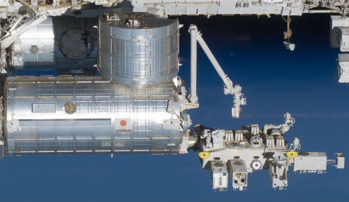
The JEM is berthed to the port side of Node 2. (Harmony)
The JEM is berthed to the port side of Node 2. (Harmony)
The Japanese Experiment Module [JEM] called Kibo (key-boh) which means "hope" is Japan's first human-rated space facility. It is the largest experiment module on the Station, accommodating 31 racks in its pressurized section, including experiment, stowage, and system racks.
Kibo is also equipped with external facilities that can accommodate 10 exposed experiment pay-loads.
The JEM is a complex facility that enables several kinds of specialized functions to perform experiment activities in space.
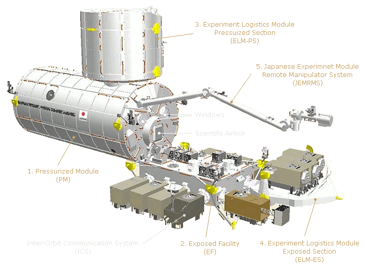
The main component of Kibo is a Pressurized Module [PM] where crew conduct the experiments and operate the facility. Permanently attached to the PM is the Exposed Facility [EF] for experiments requiring exposure to space.
Also attached to the PM is the JEM Remote Manipulator System [JEMRMS], a robot arm for manipulating items on the EF.
A pressurized module called the Experiment Logistics Module - Pressurized Section [JEM ELM-PS] is berthed to a hatch on the PM.
There is also an external platform called the Experiment Logistics Module - Exposed Section [JEM ELM-ES] berthed to the EF.
Both these components are used for storage and transport of items to and from the Station.
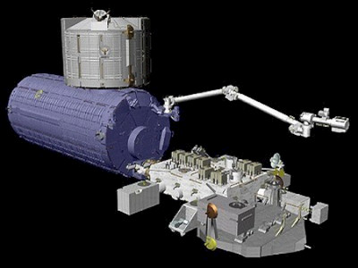
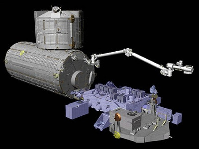
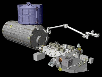
Kibo's five main components are shown on the drawing below and described briefly (right). More details are given in the sections below.
The PM is the main pressurised section of Kibo where crew conduct experiments and control the total facility. It is permanently attached to the port side of Node 2. (Harmony), which connects the Kibo to the rest of the station. The PM also supports and provides access to the ELM-PS. The EF and the JEMRMS are attached to the PM's port end.
The EF is a multi purpose experiment space for activities which are exposed to space (high level vacuum) and utilize the micro gravity environment. These include experiments in science, communications, engineering, materials and Earth observation. The EF is permanently attached to the port end of the PM.
The ELM-PS is a pressurised storage facility providing space for experiment pay-loads, samples, and spare items. It is attached to the top of, and accessed through, the PM. The ELM-PS module may be detached from the PM and returned to Earth.
The ELM-ES carries experiment pay-loads and system ORUs to and from the EF. The ELM-ES was carried to the Station by the U.S. Space Shuttle and connected to port end of the EF.
The JEMRMS is then used to transfer items to the EF when needed, and back to the ELM-ES when finished with. The ELM-ES can be detached from the EF to return items to Earth.
The JEMRMS is a robotic arm system designed to support and manipulate experiments and perform maintenance tasks on the Kibo un-pressurized facilities. It is operated from a console in the PM.
The JEMRMS is composed of two arms, a main arm (MA) for moving larger items and a small fine arm (SFA) for more delicate operations. The MA is permanently connected to the port end of the PM. The SFA is stored on the EF and attached to the end of the MA when needed.
The Kibo modules were delivered and assembled in orbit over the course of the following three U.S. Space Shuttle missions. This was because the overall size and weight of the Kibo complex is too large to deliver in a single shuttle flight.
STS-123 Endeavour [Flight 1J/A] - The ELM-PS was delivered and temporarily stored on the top of Node 2. (Harmony). The ELM-PS was later moved to a berthing port on top of the PM.
STS-124 Discovery [Flight 1J] - The PM was delivered and installed on the port side of Node 2. (Harmony). The JEMRMS was also delivered attached to the port end of the PM.
STS-127 Endeavour [Flight 2J/A] - The EF was delivered and installed on the port end of the PM. The ELM-ES was also delivered already attached to the port end of the EF.
The overall weight of the PM with all the system racks and pay-loads installed exceeds the shuttle's lift capability. All system racks, however, must be installed in the PM prior to its full activation in orbit. Therefore, some of the system racks and International Standard pay-load Racks (ISPRs) were delivered to the station on the first mission and later installed in the PM before activation.
The Inter-Orbit Communication System (ICS) gives Kibo was capability of independent communications with the Japanese Tsukuba Space Center (TKSC). It uses Japan's Aerospace Exploration Agency's (JAXA) Data Relay Test Satellite (DRTS). Commands and voice are uplinked from the ground to Kibo, and experiment data, image data or voice are downlinked to the ground for scientific pay-load operations.
The ICS uses an antenna and a pointing mechanism mounted on the EF (ICS-EF) which is used to communicate with the DRTS. This was delivered to the station, along with the EF and ELM-ES, on the STS-127 [Flight 2J/A] mission.
The ICS is operated from a rack in the PM (ICS-PM). It was delivered to the station on STS-123 [Flight 1J/A] and later installed in the PM and during the STS-124 [Flight 1J] mission.
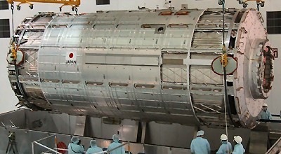
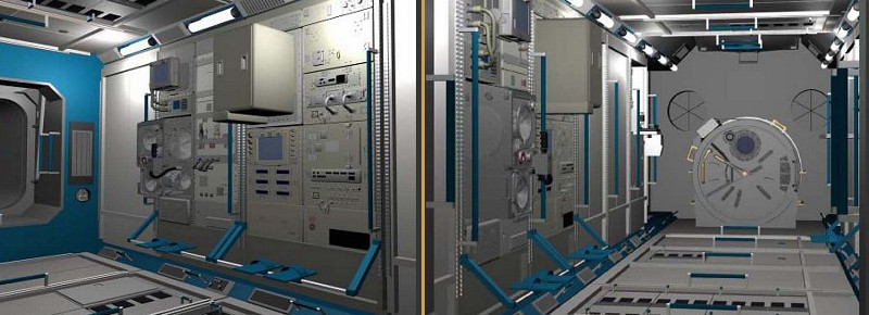
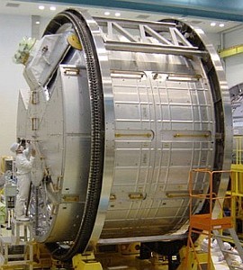
The Pressurized Module [PM] is a facility where astronauts conduct experiments and control the total Kibo facility. The air composition, pressure, temperature and humidity are controlled to be similar to Earth and comfortable for astronauts to work in a shirt-sleeve environment.
The PM is the largest pressurized module on the station, it is cylindrical in shape and about the size of a large tour bus. It can hold up to 23 racks, 10 of which are International Standard pay-load Racks (ISPRs).
Although the PM has an 8-rack equivalent length, the presence of the airlock restrict the number to 6 on the side and bottom walls.
Also the hatch for access to the ELM-PS limits racks to five on the zenith wall.
These devices are required to maintain the JEM's functions or to support crew activities. They include the power supply, communications, air conditioning, device cooling water control and experiment support.
Also included are the manipulator console used to exchange devices on the EF, the inter-satellite communication equipment and an airlock through which devices can be exchanged between the EF and PM.
Experiment devices are dedicated to conducting experiments from the public researchers. They can perform their functions only in cooperation with the System Devices stated above.
The PM contains a total of ten experiment racks equipped with mainly biological and material experiment functions. Researchers will attempt new material development or will try to solve scientific problems.
The JEMRMS is a robotic arm system designed to support and manipulate experiments and perform maintenance tasks on the un-pressurized facilities. It is operated from a console in the PM.
The JEMRMS is composed of two arms, a main arm (MA) for moving larger items and a small fine arm (SFA) for more delicate operations. The MA is permanently connected to the port end of the PM. The SFA is stored on the EF and attached to the end of the MA when needed.
Following are the general specifications of the PM.
* Shape: Cylindrical
* Outer Diameter: 4.4 m (14.4 ft)
* Length: 11.2 m (36.7 ft)
* Mass: 15.9 tons (fully assembled)
* Number of Racks: 23 (10 International Standard pay-load Racks)
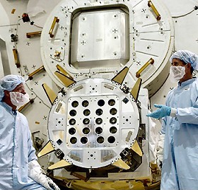
The PM has a small scientific airlock through which experiments, or orbital replacement units (ORUs), can be transferred between the PM and the EF.
The transferred item must be smaller than 460 x 830 x 800 mm and must not exceed 300kg, the mass transfer capacity of the slide table. It is not designed for space walkers.
The airlock is cylindrical and consists of an inner hatch, outer hatch and a slide table.
The inner hatch is a hinged door that the crew can manually open and close.
The outer hatch is a motorized with a door that retracts inward.
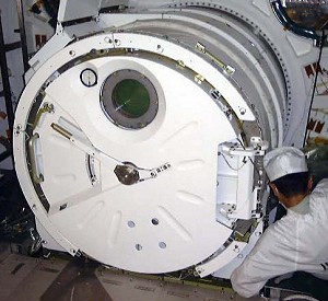
When transferring equipment to the outside, the item is fastened to the slide table and the inner hatch is sealed. After de-pressurizing the airlock, the outer hatch is opened and the slide table is extended. The equipment is then handed off to the small fine arm of the JEMRMS, and the operator can position the hardware as required.
The inner hatch contains a window for viewing the airlock pay-load. The PM is also equipped with two windows, located just above the airlock for the crew to see the Kibo un-pressurized facilities. The crew can also observe and monitor the un-pressurized facilities with external television cameras mounted on the PM.
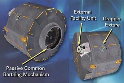
The PM external equipped includes two grapple fixtures to allow the station robot arm (Canadarm2) to grapple and move it. There is also an Active Common Berthing Mechanism (ACBM) on the zenith side of the module for attaching the ELM-PS.
The major external equipment associated with the PM are an airlock and the JEMRMS.
The PM was the second component of Kibo to be delivered to the Station. It was transported to the Station by U.S. Space Shuttle Discovery STS-124 [Flight 1J] in May 2008.
The PM is fitted with a standard Passive Common Berthing Mechanism (PCBM), similar to those used on other modules in the U.S. Segment. The PCBM was used to attach the PM to the Active Common Berthing Mechanism (ACBM) on the port side of Node 2. (Harmony).
The JEMRMS was delivered already installed on the port end of the PM.
The Exposed Facility [EF] is a multi purpose external platform utilizing exposure to space with micro gravity and high level vacuum. The facility is used for experiments in science, communications, engineering, materials and Earth observation.
The EF is used for international as well as Japanese research with pay-loads that can be exchanged allowing for various types of experiments. There are ten Equipment Exchange Units on the EF for attaching experiment pay-loads.
The EF is connected to the PM by using the Exposed Facility Berthing Mechanism (EFBM). The EF in turn supports the The Experiment Logistics Module - Exposed Section [ELM-ES] and the external component of the Inter-Orbit Communication System (ICS-EF).
The EF is planned to be operated for ten years on orbit.
* Shape: Box
* Length: 6 m (20 ft)
* Width: 5 m (16.7 ft)
* Height: 4 m (13.3 ft)
* Mass: 4,000 Kg (8,890 pounds)
* pay-loads: 10
* Power Supply: 11 kw (max) 120 V (DC)
* Thermal Control: Liquid cooling, Heater, Insulation
* Design Life: 10 years
* Length: 1.85 m (6.2 ft)
* Width: 1.0 m (3.3 ft)
* Height: 0.8 m (2.7 ft)
* Mass: 500 Kg (1,110 pounds)
Following are some of the main components of the EF.
A mechanism which connects the EF to the PM.
The Power system, Communications, Command and Control system and thermal control system are connected through this mechanism. The active half of the berthing mechanism (EFBM-A) is located on the PM endcone, and the passive half (EFBM-P) is located on the EF.
The EF accommodates ten experiment units, which are connected to EF by Equipment Exchange Units (EEU).
A mechanism which connects experiment units to EF. It provides connections to the Power system, communication/control system and thermal control system. Being able to exchange the experiment units by means of EEU allows a greater variety of experiments and can accommodate future engineering evolution in a flexible manner.

These are used to fix the EF in the U.S. Space Shuttle's cargo bay for transport to the Station.
Consists of a TV camera, light and Pan/Tilt unit. It provides views of experiment pay-loads or ORUs when they are being moved by Kibo's robot arm [JEMRMS].
The JEM robot arm [JEMRMS] consists of a main arm (MA) to move larger items and a small fine arm (SFA) which can be attached to the end of the MA when needed for fine manipulation tasks. The SFA is stowed on the EF until needed.
Components designed to be exchanged on orbit, either inside or outside of the Station. Some of the ORUs are designed for exchanging by using the EF and Kibo's robot arm (JEMRMS).
The JEM Experiment Logistics Module - Pressurised Section [ELM-PS] is a storage facility that provides space for experiment pay-loads, samples, and spare items. Its pressurized interior is maintained at one atmosphere, thus providing a shirt-sleeve working environment. The crew are able to move freely between the ELM-PS and the Pressurized Module [PM].
The ELM-PS volume is less than the PM and can only house eight racks.
When it was launched aboard the U.S. space shuttle it was used for transporting racks to the station. These comprised of five sub-system racks, two experiment racks, and one stowage rack.
The sub-system racks were for use in the PM, but could not be launched with it because this would overload the Shuttle's lifting capacity.
These racks were therefore launched with the ELM-PS and moved to the PM after its installation on the station.
* Shape: Cylindrical
* Outer Diameter: 4.4 m
* Inner Diameter: 4.2 m
* Length: 4.2 m
* Mass: 18,490 pounds
* Number of Racks: 8
* Power Need: 3 kW 120 V DC
* Temperature: 18 - 29 deg. C
* Humidity: 25 to 70 %
* Design Life: 10 years plus
The ELM-PS was the first component of Kibo to be delivered to the Station. It was transported to the Station by U.S. Space Shuttle Endeavour STS-123 [Flight 1J/A] in March 2008 and temporarily stored on the top of Node 2. (Harmony).
The ELM-PS is fitted with a standard Passive Common Berthing Mechanism (PCBM), similar to those used on other U.S. Segment modules. The PCBM attaches to the Active Common Berthing Mechanism (ACBM) on the zenith berthing port of the Pressurized Module [PM].
The ELM-PS was moved to its normal position on the zenith port of the PM after the PM was installed on the Station in May 2008.
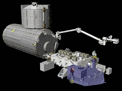
The JEM Experiment Logistics Module - Exposed Section [ELM-ES] is a component which carries and stores Exposed Facility [EF] experiment pay-loads and system Orbital Replacement Units (ORUs).
The JEMRMS robot arm is used to transfer items to the EF when needed, and back to the ELM-ES when finished with. The ELM-ES can be detached from the EF and secured in the Shuttle to return items to Earth and bring new ones back to the station.
* Shape: Frame
* Length: 4.2m
* Width: 4.9m
* Height: 2.2m (includes pay-loads)
* Weight: 1.2t (dry)
* Experiment racks: 3 (EF standard)
* Experiment pay-loads: 3
* Power Supply: 1.0kw (max) 120V DC
* Thermal control: Heater, insulation
* Environment control: None
* Design Life: 10 years
The ELM-ES was the last component of the JEM to be delivered to the station. It was transported by U.S. Space Shuttle Endeavour STS-127 [Flight 2J/A] in July 2009 and attached to port end of the EF.
The ELM-ES is composed of five primary subsystems: structural, mechanical, power, communication and thermal control.
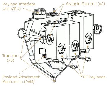
The design of the ELM-ES structure considers load factors such as those imposed during launch and retrieval by the Space Shuttle and those imposed on orbit. It has five attachment points for securing it in the pay-load bay of the Space Shuttle during transport to and from the Station. Its main structure is composed of a grid shaped panel/frame to facilitate the attachment of experiment pay-loads. The ELM-ES accommodates three exposed pay-loads, each weighing a maximum of 500kg.
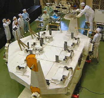
The ELM-ES is equipped with pay-load Attachment Mechanisms (PAMs) which secure experiment pay-loads to the Structural Subsystem during transport to and from the Station by the Space Shuttle.
The PAMs also support attaching and detaching pay-loads on orbit by the Kibo robot arm. Each PAM has an electric connector which supplies power to the experiment pay-loads.
The ELM-ES power subsystem is supplied 120Vdc power by the EF power subsystem.
It then distributes a maximum of 1kW of power to system equipment and experiment pay-loads through the Power Control Unit (PCU).
The communication sub-system is controlled by the Pressurized Module (PM) control system through the Electric Control Unit (ECU). It monitors the status of the ELM-ES, performs power control and PAM torque control, and controls the temperature for equipment including experiment pay-loads.
The ELM-ES is covered with Multi Layer Insulation (MLI) to prevent excessive cooling due to heat loss in the low-temperature environment. System equipment or experiment pay-loads can also be warmed by a heater where the MLI is unable to sustain the required thermal conditions.
The JEM Remote Manipulator System [JEMRMS] is a robotic arm system designed to support and manipulate experiments and perform maintenance tasks on the JEM un-pressurized facilities.
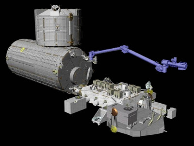
The JEMRMS is composed of two arms, a 10m long Main Arm (MA) and a shorter 2m long Small Fine Arm (SFA). The MA is primarily used to transfer large objects, and the SFA to handle the smaller, more delicate items. Both arms have six independent joints and provide dexterity in movement, similar to the human arm.
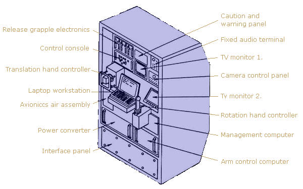
The MA is permanently connected to the port end of the Pressurized Module [PM]. The SFA is stored on the Exposed Facility [EF] and attached to the end of the MA when needed. The robotic control workstation in the PM, known as the JEMRMS Console, is used for manipulating the arms. Remote television cameras are mounted on both arms to assist in their control.
The arms are used to exchange exposed pay-loads and ORUs between the EF and the Experiment Logistics Module - Exposed Section [ELM-ES]. They are also used to place and remove items on the PM's scientific airlock tray.
The JEMRMS is designed to operate for more than 10 years in orbit and incorporates a modular design which allows many major components to be exchanged or replaced in case of failure.
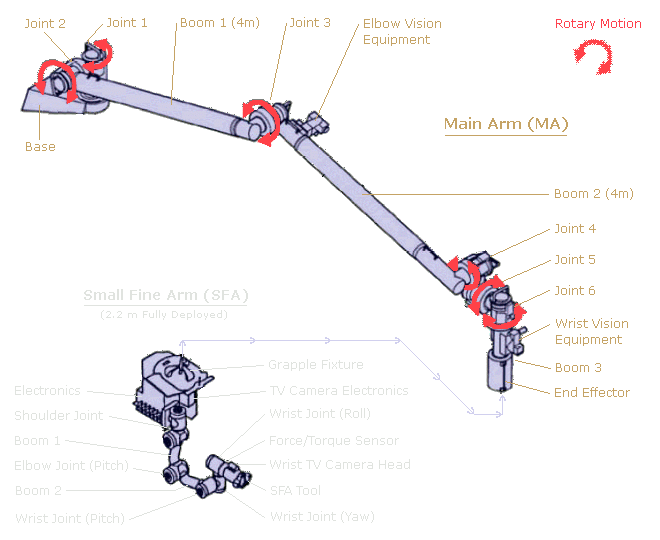
* Degrees of freedom: 6
* Length: 9.9 m
* Pay-load handling weight: 7,000 kg (max)
* Positioning accuracy - Translation: 50 mm (+/-)
* Positioning accuracy - Rotation: 1 degree (+/-)
* Translation/rotation speed - P/L less than 600kg: 60 mm/s
* Translation/rotation speed - P/L less than 3000kg: 30 mm/s
* Translation/rotation speed - P/L less than 7000kg: 20 mm/s
* Maximum tip force: 30 N
* Design Life: 10 years
* Degrees of freedom: 6
* Length: 1.7 m
* Pay-load handling weight: 300 kg (max)
* Positioning accuracy - Translation: 10 mm (+/-)
* Positioning accuracy - Rotation: 1 degree (+/-)
* Translation/rotation speed - P/L less than 80kg: 50 mm/s
* Translation/rotation speed - P/L less than 300kg: 25 mm/s
* Maximum tip force: 30 N
* Design Life: 10 years
The JEMRMS was transported to the station by U.S. Space Shuttle Discovery STS-124 [Flight 1J] in May 2008. It was delivered already installed on the port end of the PM.
The SFA was delivered on a later mission.