U.S. Space Shuttle (Space Transport System)
technical - orbiter vehicle (ov)
U.S. Space Shuttle (Space Transport System)
technical - orbiter vehicle (ov)
The Orbiter Vehicle (OV) is the main component of the U.S. Space Shuttle (Space Transport System). It is launched like a rocket, can manoeuvre in Earth orbit like a spacecraft and lands like an aeroplane.
The Shuttle is launched vertically, like a conventional rocket, with the two Solid Rocket Boosters (SRBs) operating in parallel with the Orbiters three main engines (SSMEs).
These are fuelled from the the External Tank (ET) containing liquid hydrogen and liquid oxygen. The SRBs are jettisoned before the vehicle reaches orbit, and the ET is jettisoned just before orbit insertion.
References: NASA The Orbiter | Wikipedia: Shuttle Orbiter, Shuttle Main Engine
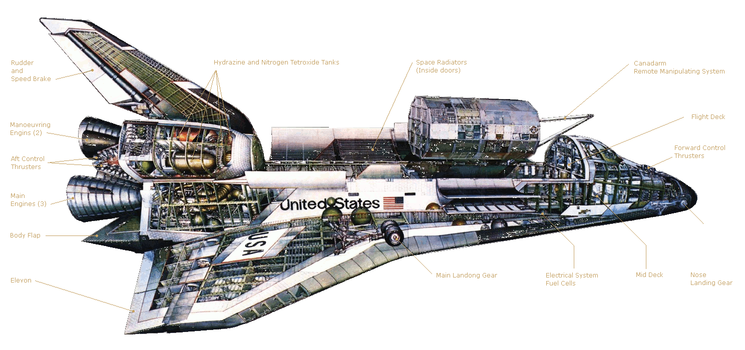
The orbiter fuselarge consists of three main sections:
Forward (nose section) - Pressurized crew module and cockpit.
Mid (payload bay) - Carries the major cargo of the mission.
Aft (tail section) - Contains the shuttles main engines.
Details are given below.
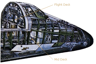
The forward fuselage contains the pressurized crew module with cockpit, living quarters and experiment operator's station. It also provides support for the nose section, the nose gear and the nose gear wheel well and doors.
Crew members include pilot astronauts, called the commander and pilot who fly the shuttle, and mission specialist astronauts who are scientists and engineers trained to conduct the experiments on-board or perform specific tasks in orbit. Occasionally the crew also may include payload specialist astronauts in charge of the operations of a specific cargo.
The cabin includes a circular side hatch, about a meter (3 feet) in diameter, that is used for entry and exit from the shuttle before launch and after landing.
The crew station module is a three-section pressurized working, living and stowage compartment. It has two levels consisting of a Flight deck and a Mid deck / equipment bay.
The Flight Deck has a commander's seat positioned on the left and a pilot's seat on the right and two seats behind. The vehicle may be piloted from either front seat and permits one-man emergency return. Each seat has manual flight controls, including rotation and translation hand controllers, rudder pedals and speed-brake controllers.
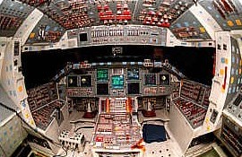
The on-orbit displays and controls are at the aft end of the flight deck/crew compartment. The displays and controls on the left are for operating the orbiter, and those on the right are for operating and handling the payloads. There are more than 2,020 separate displays and controls located on the flight deck.
Six pressure windshields, two overhead windows and two rear-viewing payload bay windows are located in the upper flight deck.
The main components of the Mid fuselage are the payload bay and the Remote Manipulator System (RMS).
Payloads are the major cargo carried by the shuttle into orbit. They include satellites, Space Station components and experiments. Payloads may be attached directly to the orbiter or to carriers that are attached to the payload bay.
Payloads for the International Space Station have included:
* All U.S. Segment assembly components,
* Spacehab Logistics Module - Pressurised cargo module.
* Integrated Cargo Carrier - Un-pressurised cargo pallet.
* MPLM (Multi-Purpose Logistics Module) - Contains supplies and equipment for the space station.
Each payload bay door supports four radiator panels to provide cooling for shuttle components while in orbit. When the doors are opened, the four forward radiators are unlatched and tilted to the proper position. This allows heat radiation from both sides of these panels. The four aft radiator panels radiate from the upper side only.
The Remote Manipulator System (RMS), also called the Shuttle Robot Arm or Canadarm, is a 15.2-meter (50-foot) long articulating arm remotely controlled from the flight deck of the orbiter. The elbow and wrist movements permit payloads to be grappled for deployment out of the payload bay or retrieved and secured for return to Earth.
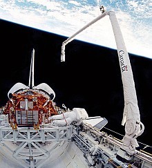
A television camera and lights near the outer end of the arm let the operator to see on monitors what the arm is doing. Three flood lights are also located along each side of the payload bay.
The RMS was built for NASA in Canada a "Partner" country of the International Space Station.
The aft fuselage consists of:
* Space shuttle main engines (SSME),
* Orbital manoeuvring systems (left and right),
* Body flap,
* Vertical tail,
* Orbiter/external tank rear attachments.
The forward bulkhead of the aft fuselage closes it off from the mid fuselage. The upper portion of the bulkhead attaches to the vertical tail. The internal thrust structure supports the three space shuttle main engines, low pressure turbo-pumps and propellant lines.
The three main engines of the space shuttle, in conjunction with the solid rocket boosters, provide the thrust to lift the orbiter off the ground for the initial ascent.
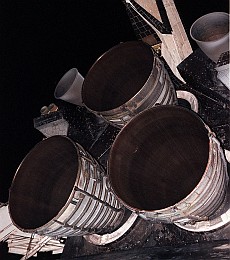
The main engines continue to operate for 8.5 minutes after launch, the duration of the shuttle's powered flight.
After the solid rockets are jettisoned, the main engines provide thrust which accelerates the shuttle from 4,828 kph to over 27,358 kph in just six minutes to reach orbit. They create a combined maximum thrust of more than 1.2 million ft-pounds.
As the shuttle accelerates, the main engines burn a half million gallons of liquid propellant provided by the External Fuel Tank. This consists of liquid oxygen and liquid hydrogen at a mixture ratio of 6 to 1 by weight.
The hydrogen and oxygen can reach a temperature of 3,315 degrees Celsius as they burn. This is higher than the boiling point of iron.
The engines therefore operate at greater temperature extremes than any other piece of machinery ever built.
The nominal maximum crew size is seven. The mid deck can be reconfigured by adding three rescue seats in place of the modular stowage and sleeping provisions. The seating capacity will then accommodate the rescue flight crew of three and a maximum rescued crew of seven.
The Mid deck / equipment bay contains provisions and stowage facilities for four crew sleep stations; stowage for the lithium hydroxide canisters and other gear; waste management system; personal hygiene station; work/dining table. A window is located in the crew entrance/exit hatch located in the Mid deck.
A small lower "deck," called the equipment bay, is inaccessible unless the floor panels of the mid-deck are lifted up. This under-floor area houses avionics equipment, electronics equipment and a trash compartment.
On missions that require the crew to perform space walks, known as extravehicular activity, or EVA an airlock is provided between the pressurized crew module and the payload bay (mid fuselage).
The airlock can be located in one of several places:
* Inside the orbiter crew module in the mid deck area mounted to the aft bulkhead,
* Outside the cabin also mounted to the bulkhead,
* On top of a tunnel adapter that can connect the pressurized Spacehab module with the orbiter cabin.
* Included in a docking module.
The airlock contains two spacesuits with expendables for two six-hour payload EVAs and one contingency or emergency EVA. It also contains mobility aids such as handrails to enable the crew to perform a variety of tasks. The airlock allows two crewmen room for changing spacesuits. An inner airlock hatch can be closed to seal the lock from the rest of the cabin. An outer hatch can be opened to exit into space. A docking mechanism to attach to the International Space Station may be located atop the airlock.
The general specifications for a typical orbiter are:-
Height: (on runway) 17.3 meters (56.6 feet)
Length: 37.2 meters (122.2 feet)
Wingspan: 23.8 meters (78.1 feet)
Weight - Gross Lift off: 110,000 kg (240,000 lb)
- Maximum Landing: 100,000 kg (230,000 lb)
- Maximum Payload: 25,060 kg (55,250 lb)
- Return Payload: 14,400 kg (32,000 lb)
Orbit - Range: 190 to 960 km (120 to 600 miles)
- velocity: 27,875 kph (17,321 mph)
Mission Duration: 5 to 16 days
Crew Module: 65.8 cu. meters (2,325 cu. feet)
Crew Size: 2 to 8 (normally 5 to 7)
Airlock Volume: 4.24 cu meters (150 cu. feet)
Mid Fuselage - Length: 18.3 meters (60.0 feet)
- Width: 5.4 meters (17.4 feet)
- Height: 4.0 meters (13.0 feet)
Payload Bay Doors - Length: 18.3 meters (60.0 feet)
- Diameter: 4.6 meters (15.0 feet)
- Width: 6.9 meters (22.7 feet)
- Surface: 148.6 sq. meters (1,600 sq. feet)
Aft Fuselage - Length: 5.5 meters (18.0 feet)
- Width: 6.7 meters (22.0 feet)
- Height: 6.1 meters (20.0 feet)
Body Flap - Area: 12.6 sq. meters (135.8 sq. feet)
- Width: 6.1 meters (20.0 feet)
Main Stage (SSME with external tank)
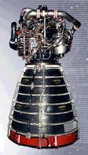
- Engines: Three Rocketdyne Block II SSMEs
- Thrust: (all 3 engines at lift off) 1,181,400 lbf (5,255 kN)
- Specific impulse: 455 seconds (4.46 km/s)
- Burn time: 480 seconds
- Fuel: Liquid Hydrogen/Liquid Oxygen
Orbital manoevring System
- Engines: 2 OMS Engines
- Thrust: 53.4 kN (12,000 lbf) combined total vacuum thrust
- Specific impulse: 316 seconds (3.10 km/s)
- Burn time: 150-250 seconds (typical), 1250 seconds (deorbit)
- Fuel: MMH/N2O4
The engines' exhaust is primarily water vapor as the hydrogen and oxygen combine. The thrust is developed in a staged combustion cycle. The propellants are partially combusted in dual pre-burners to produce high-pressure hot gas to drive the turbo-pumps. Combustion is completed in the main combustion chamber. Temperatures in the main engine combustion chamber can reach as high as 6,000 degrees Fahrenheit (3,315.6 degrees Celsius).
Each main engine is 4.27 m (14 ft.) long and 2.29 m (7.5 ft.) wide at the mouth of the nozzle and produces a sea level thrust of 179,097 kg (375,000 pounds) and a vacuum thrust of 213,188 kg (470,000 pounds).
They can be throttled over a thrust range of 65 percent to 109 percent. This provides for a high thrust level during lift off and the initial ascent phase but allows thrust to be reduced to limit acceleration to 3 g's during the final ascent phase.
The engines are gimbaled to provide pitch, yaw and roll control during the ascent. They have a life of 7.5 hrs. and 55 starts.
The first four flights of the shuttle were used mainly to test the operation and systems for launch and orbital flight. A number of instrument packages were carried in the shuttle orbiters payload bay to assist with these tests. Some of these packages are summarized below. General science research was also performed during these flights.
From the fifth flight on the shuttle was said to be operational. Testing and crew training, however, continued. Following the loss of shuttle Columbia in 2003 extra testing was carried on every flight to check for damage during launch.
Contained sensors and measuring devices to record the orbiter's performance and the stresses that occurred during launch, ascent, orbital flight, descent and landing to verify the orbiter's spaceworthiness.
Contains equipment for recording temperatures, pressures and acceleration levels at various points on the vehicle.
Testing of the Canadian built 'Canadarm', the Shuttle's robot arm for moving items to and from the payload bay.
A desk-sized detector containing 10 instruments for contaminants in and around the Space Shuttle orbiter cargo bay which might adversely affect delicate experiments being carried aboard.
Mounted on the end of the Shuttle's robot arm, it was designed to obtain information on gases or particles being released by the orbiter in flight.
A payload bay package to help astronauts gain experience in using the orbiter Remote Manipulator System (RMS), called Canadarm. The PFTA is an aluminum structure resembling two wheels with a six-meter long central axle, ballasted with lead for a total mass of 3,855 kg. This was lifted by Canadarm and moved around to help astronauts gain experience in using the RMS.
A set of instruments on a 50-foot (15 m) extension attached to the shuttle robot arm. The instrument package consists of visual imaging equipment and a Laser Dynamic Range Imager (LDRI) to detect problems with the shuttle's Thermal Protection System (TPS). The crew scanned the leading edges of the wings, the nose cap, and the crew compartment for damage, as well as other potential problem areas engineers wished to inspect based on video taken during lift-off.
Ref: Wikipedia Orbiter Boom Sensor System